

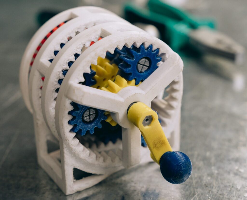
With the advent of additive manufacturing, any shape is possible as the parts are built layer-by-layer. This is a great solution for prototyping and low volme parts. One part, or set of parts, if they are small, can be made within several hours, but each part is quite expensive. When parts are needed in production quantities and/or unit price matters, designers turn to injection molding. What can be fabricated through additive manufacturing processes cannot always be molded and the design approach needs to be modified.
The intent of this guide is to be an insight into the thought process necessary to create detailed injection molded parts that are manufacturable in a production environment. We will look at some critical design features, possible secondary operations for efficient manufacturing and what can go wrong in manufacturing.
Design Purpose
As with any design project, capture the goals of the part and the requirements it needs to be meet before beginning.
Goals of the Part Design
Prioritize the key use of the part. Generally, plastic parts are used for these primary purposes:
- Protecting electronics from moisture or debris
- Preventing tampering with the electronics or mechanisms by the user
- Providing an interface or handling by the user
- Structural protection or support
Design Requirements
Identify additional requirements that influence all design decisions:
- RoHS
- WEEE
- FCC, FAA, FDA
- Regulatory (UL, CSA, CE)
- EMI
Production Volume vs. Complexity
While additive manufacturing allows for very complex surfaces and designs to be fabricated into a single part, injection molding needs to consider how the part will be removed from the mold. Some parts can be combined while others need to be separated into halves for secondary joining after the molding process.


Design Considerations
Tooling
The heart of injection molding are the tools used to fabricate the parts. There are different tooling options depending upon the volume, complexity, timeframe, and budget.
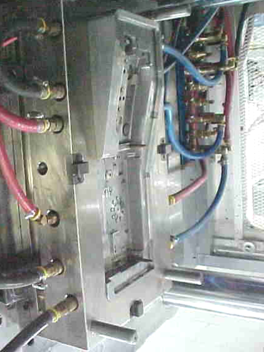
Tooling Materials
Steel
- Extended life 300,000 shots or more
- Can maintain tight tolerances
- Longer timeframe to fabricate the tool
Aluminum
- Limited life due to wear, 10,000’s of shots
- Not for tight tolerance parts
- Faster timeframe for tooling fabrication
Tooling Options

Slides & Lifters
- When features are not accessible in the primary pull direction (open/ closing of the mold), slides or lifters need to be added to the mold. They move when the mold is closed and add cost to the cost of the tool.
- Slides are for features on the outisde of the part
- Lifters are for features on the inside of the part
Insert Molding
- This is a useful method for installing hardware like threaded inserts or artwork like lettering on computer keyboards as part of the molding process instead of secondary operations
- The hardware or sheet of lables are installed in the mold when it is open and then molten plastic is flowed around or onto it when it is closed
- For exceptionally high volumes, this can be automated with robotic loading/ unloading and eliminating secondary operations later in the process
Overmolding
- This is also referred to as a “two shot” processes because the parts are fabricated using 2 molds
- A second color or material added to the part (e.g., soft touch on computer mice) or hardware elements (e.g. decorative plates) can be molded into the plastic
- Materials must be compatible with each other (mold temperature, material)
Types of Tooling
Prototype
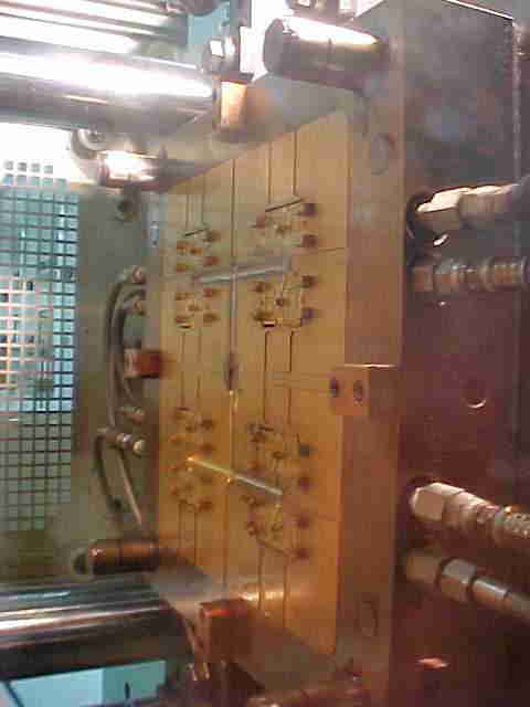
- Typically made from aluminum for quick turn
- May last for upwards of 10,000 shots
- Considered disposable
Production
- Made from tool steel to maintain tolerances over its lifetime
- High volumes of upward of 1,000,000 shots
- Many weeks or a few months to fabricate
Bridge
- Intended to “bridge the gap” between prototypes and production
- Typically made from aluminum or mild steel
- May last for upward of 100,000 shots
Multi-cavity
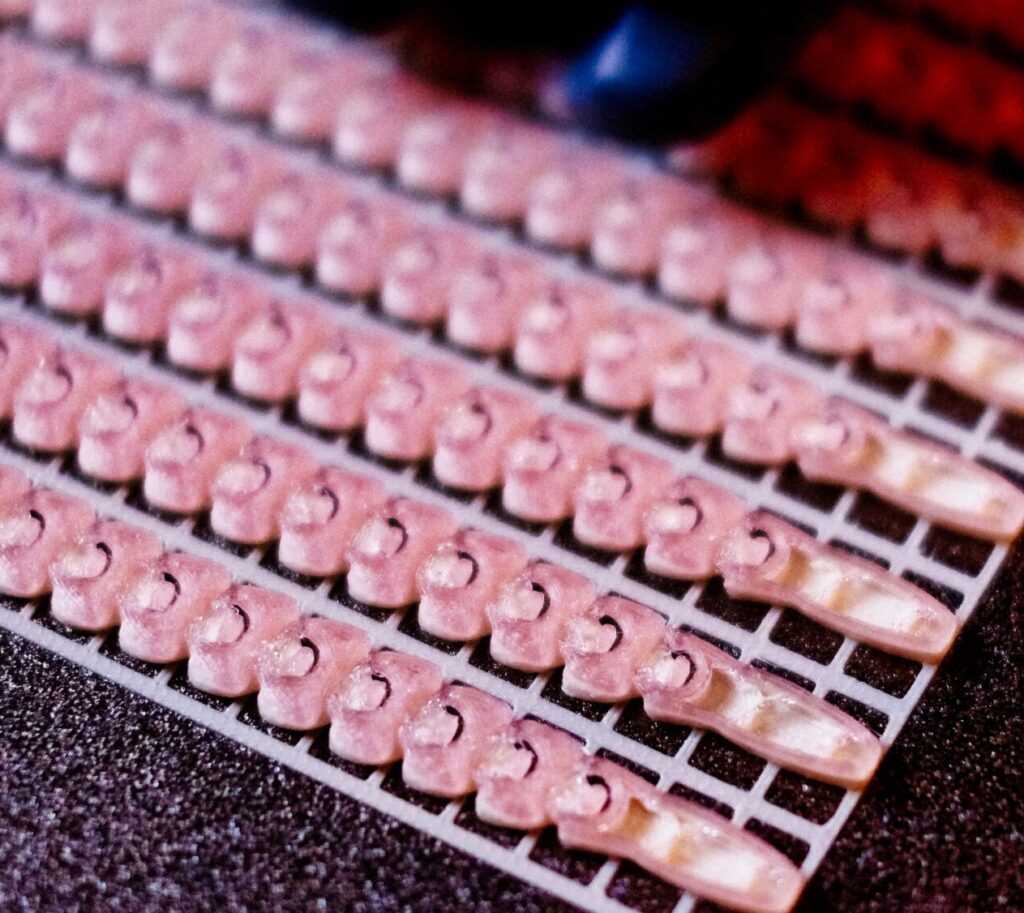
- Typically used for higher production volumes
- A tool with multiples of the same part shot at one time
- Great for high volumes as it reduces cycle time per part
Family
- A varation of a multi-cavity tool with different parts shot at one time
- Part need to be similarly sized to avoid molding issues
- Tool may have shutoffs to isolate parts if volumes are not evenly matched
Cost
The cost of the tooling is dependent upon several factors:
- The size of the part
- Prototype vs. production tools
- Single or multi-cavity
- The number and complexity of critical features and dimensions
- Wall thickness
- Pull direction of the tool, where a single pull is lowest cost and slides and lifters add complexity and cost

Secondary Operations
After the parts are molded, many times there are additional processing steps for assembly or appearance needed to get to the final part.
Degating
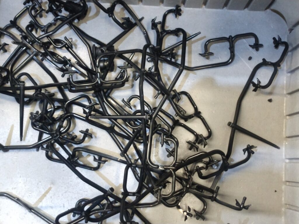
Parts are typcially molded with runners, which need to be removed, typically when the parts are still warm to avoid stress-induced cracking. This can be done through several methods:
- In-mold pullers
- Snipping or clipping
- Ultrasonic machine or handheld knife
If too much of the gate remains after the runner is removed the parts may need to be sanded, ground, or further trimmed to avoid sharp edges.
Finishing
Textured surfaces are used to remove molding tooling marks, achieve the desired cosmetic appearance or tactile feel of a part. The finish of the part comes in grades A- D ranging from a mirror finish to textured.
- High gloss, mirror or optical finishes are needed for lenses and other high performance parts
- Semi-gloss, fine, or smooth finish are typical where machine marks need to be removed such as in consumer goods
- Matte, stone or dull finish are usefule where glare or bright reflections need to be minimized or fingerprints from handling need to not visible.
- Textured, rough, or grained finishes are common where grip is important or parts need to be scratch resistant
A combination of finishes may be necessary, but it substantially increases the cost of the part.
CAUTION: depth or roughness of texture may need more draft angle to release properly from the mold.
Hardware
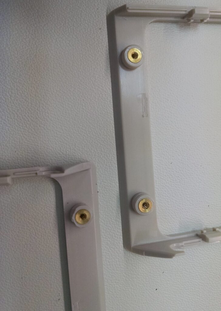
Many times metal hardware such as threaded inserts need to be installed into the plastics for mounting other components or joining plastic parts together. The common methods for installing these are:
- Insert molded – this is done as part of the molding process and not secondary. Typically the parts are SI or equivalent
- Swaged – threaded inserts are pressed into shallow holes, such as PEMs or equivalent
- Thread forming – inserts have threads that are designed to minimize plastic deformation and lock hardware in place, such as Plastite or equivalent
NOTE: avoid countersink hardware, especially close to edges as the radial forces wil cause the plastic to fracture.
Joining
When plastic parts need to be assembled together, there are several ways to do this depending on the need for them to be reworkable and taken apart as well as the materials used.
- Fastened together
- Either with thread-forming or machine screws into threaded inserts
- Typically this design enable rework and disasembly
- Welding
- Requires special features, tooling, and equipment
- Typically this design is permanent attachment and destructive disassembly
- There are several kinds of welding depending on what features are possible, the size of the welds needed, and the materials used
- Hot plate welding – the surfaces to be joined are heated by a hot plate to the point just over the melt temperature and the parts are placed together. When the parts are cool they form a secure bond.
- Friction welding – this is also know as ultrasonic and vibration welding where friction is used to heat up the weld surfaces. Pressure can be applied to aid in joining the surfaces.
- Laser welding – the surfaces are heated with a laser while in contact with each other to allow for the heat to transfer between the parts. Material selection is important to obtain good results as one part needs to be transparent allowing the laser to plass through it, while the other is opaque, typcially black, to absorb the heat.
Design Criteria
General Guidelines
Materials
- The product requirements will guide the options for materials and the material selected can impact the dimensions.
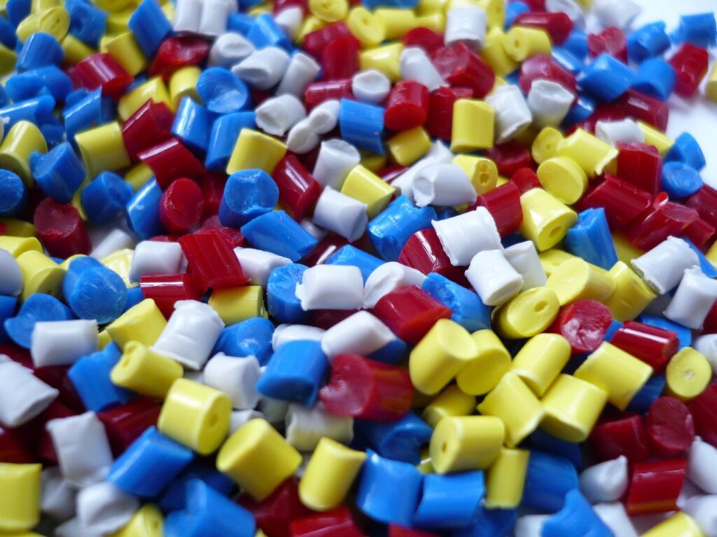
- Utilize common materials when possible, such as polycarbonate, polypropolene or ABS, to keep costs down. Specialty materials exist if needed, but will increase the cost of the part.
- Glass fibers can be added for strength and dimensional stability, but will also increase the wear on the tool.
- When overmolding 2 materials, consider how the two materials will interact in the molding process.
Tolerances
With the advent of 3D CAD many designers believe drawings are irrelevant, but they are the only place to specify the part requirements not native to the CAD files. The CAD is designed at nominal dimensions, but in manufacturing the actual parts are going to be some measurable amount away from nominal. The drawings communicate which dimensions are important for the parts to fit together and function as expected.
- Use tight tolerances sparingly as overconstrained parts will reduce yield and increase cost. A typical starting point for small to medium-sized parts is +/-0.13mm (+/-0.005″).
- Material shrink can limit how tight tolerances can be, especially on larger parts.
- Have a minimum number of “control” dimensions on the drawings to monitor tool wear and sample for process control.
Moldability Guidelines
Draft Angles & Undercuts
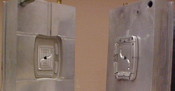
In order to remove parts from the mold, walls need to have a slight inward angle toward the bottom of the mold.
- Typically, 0.5-deg to 3.0-deg, depending on design, material, and texture. A coarser texture will require a larger draft angle.
- Utilize CAD tools to ensure draft angles are angled in the right direction.
- Where possible, avoid undercuts, those features which require lifters or slides for molding. This adds to the cost of the tool and increased maintenance.
Part Thickness
The thickness of a part balances the strength required with dimensional constraints. Walls that are too thin may not fill entirely and parts that are too thick may get sink marks.
- Walls
- Walls should be around 2-5mm (0.075″-0.200″)
- The thickness of the wall is dependent upon how tall it is and the material used
- Ribs
- Ribs can be used to stiffen the part and reduce weight
- Ribs are either freestanding or conneted to closest wall for support
- Ribs should not exceed 80% of the base thickness and typically have a height that is 60-70% of connected base
Issues to Avoid
Some common defects created during injection molding are caused by the design of the part, the machine process parameters, tool design, or a combination of any of these.
Bow & Twist
- A part that isn’t as flat or straight as expected
- Caused by imbalanced construction where one side of the part cools faster than the other. This typically happens when one side of the part has significantly more mass than the other.
- Mitigating bow and twist can be done by changing the flow of the material into the mold or designing the part in 2 pieces for assembly as a secondary operation.
Knit Lines
- A line in the molded plastic where two plastic wavefronts meet when the part is filled with molten plastic.
- In optical parts it can impact performance. In non-optical parts the plastic may be cooled slightly below molton resulting in a poorly bonded area.
- This can be mitigated by changing the size of the gate, increasing mold temperature, or moving the gate to a different fill location.
Sink
- Typically in a thicker portion of the plastic, the surface can have a sunken appearance.
- This happens when thick areas of plastic cool slower than thinner areas.
- Mitigating sink can be done by using ribs and other features to increase or maintain rigidity while reducing part thickness.
Incomplete Fill
- When a part doesn’t have all of the features and appears like portions are cut off.
- This happens in very thin sections of the part where the molten plastic cools down too much before it flows into the thin regions or there is inadequate venting to allow the air in the mold to escape.
- Mitigating incomplete fill can be done by adding additional gates into the thin region or increasing the venting.